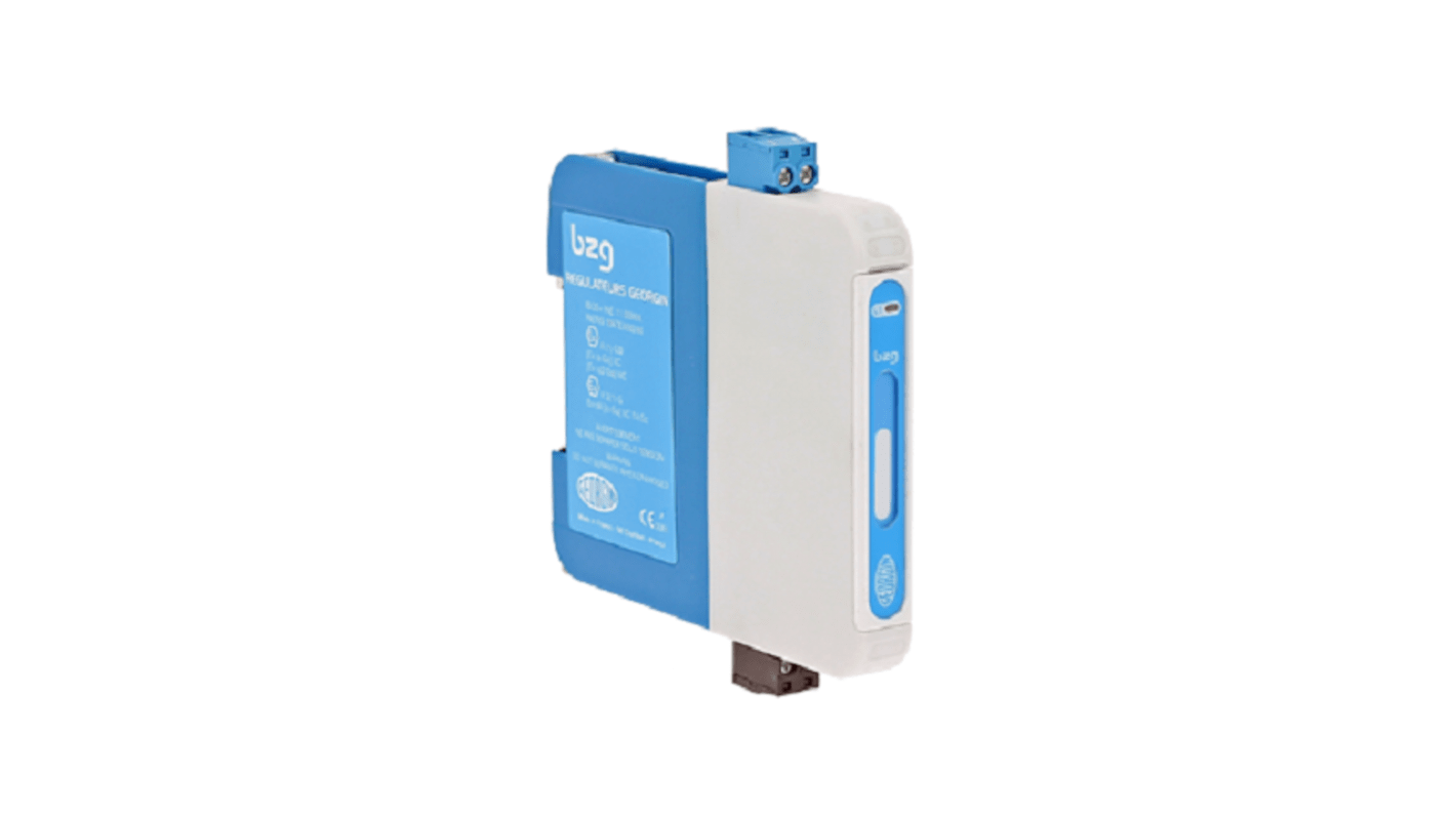
GEORGIN 1 Channel Double Zener Barrier, ATEX
- RS Stock No.:
- 230-9454
- Mfr. Part No.:
- BZG760AC
- Manufacturer:
- GEORGIN

Subtotal (1 box of 1 unit)**
SGD235.51
(exc. GST)
SGD256.71
(inc. GST)
2 In stock for delivery within 5 working days*
* Delivery dates may change based on your chosen quantity and delivery address.
FREE delivery for orders over SGD250.00 (ex GST)
Box(es) | Per Box |
|---|---|
| 1 + | SGD235.51 |
**price indicative
- RS Stock No.:
- 230-9454
- Mfr. Part No.:
- BZG760AC
- Manufacturer:
- GEORGIN
Find similar products by selecting one or more attributes.
Select all | Attribute | Value |
|---|---|---|
| Manufacturer | GEORGIN | |
| Number of Channels | 1 | |
| Barrier Type | Zener Barrier | |
| Maximum Voltage | 5,64V | |
| Hazardous Area Certification | ATEX | |
| Maximum Current | 63,1mA | |
| Maximum Operating Temperature | +60°C | |
| Minimum Operating Temperature | -20°C | |
| Series | BZG | |
| Operating Temperature Range | -20°C to 60°C | |
Select all | ||
|---|---|---|
Manufacturer GEORGIN | ||
Number of Channels 1 | ||
Barrier Type Zener Barrier | ||
Maximum Voltage 5,64V | ||
Hazardous Area Certification ATEX | ||
Maximum Current 63,1mA | ||
Maximum Operating Temperature +60°C | ||
Minimum Operating Temperature -20°C | ||
Series BZG | ||
Operating Temperature Range -20°C to 60°C | ||
Related links
- GEORGIN 1 Channel Double Zener Barrier, ATEX
- GEORGIN 2 Channel Zener Barrier, ATEX
- Pepperl + Fuchs 1 Channel Zener Barrier, ATEX
- Eaton 1 Channel Zener Barrier Analogue Output, ATEX
- Pepperl + Fuchs 2 Channel Zener Barrier, ATEX
- Pepperl + Fuchs 3 Channel Zener Barrier, ATEX
- Eaton 1 Channel Zener Barrier Current Input, ATEX
- Eaton 1 Channel Zener Barrier RTD Current ATEX