- Published 20 Aug 2024
- Last Modified 20 Aug 2024
- 10 min
Understanding Shunt Resistors in Electrical Circuits

Explore the essential aspects of shunt resistors, including their applications in circuits, how they work, and detailed instructions for wiring and calculations in this informative guide.
What are Shunt Resistors?
Shunt resistors are essential electrical components that create a low-resistance pathway for electric current within a circuit. Their primary function is to enable the measurement of high currents by allowing a small portion of the current to flow through a measurement device, such as an ammeter. Often referred to as ammeter shunts or current shunt resistors, these devices play a critical role in various applications, including over-current protection, battery management systems, and motor control.
The term "shunt" originates from the concept of diverting or guiding electrical flow along a predetermined path. In practical terms, shunt resistors are designed to have a very low resistance, which minimises the impact on the overall circuit while ensuring accurate current measurements. They are typically constructed from materials with a low-temperature coefficient of resistance, allowing them to maintain consistent performance across a wide range of temperatures.
What Does a Shunt Do?
An electrical shunt is a specialised device designed to facilitate the flow of current through a circuit by creating a low-resistance pathway. This allows the current to either pass through or be diverted past a specific point in the circuit, enabling accurate measurements and protection mechanisms. Shunts are commonly integrated into various measurement devices, including ammeters, which can measure both direct current (DC) and power in watts.
Shunt resistors operate based on Ohm’s Law, which can be expressed with the equation:
V = I × R
In this equation, V represents the voltage across the shunt resistor, I is the current flowing through it, and R is the resistance value of the shunt in ohms. For instance, if a shunt resistor has a resistance of 0.002 ohms and carries a current of 30 amps, it will generate a voltage drop of 0.06 volts (or 60 millivolts). This voltage drop can be measured and used to calculate the current flowing through the circuit.
To measure the current flowing through a circuit, a current shunt is integrated into the circuit setup. By assessing the voltage drop across the shunt, one can determine the current using the formula derived from Ohm's Law. This method is crucial for calibrating the shunt resistor and ensuring accurate current measurements.
Shunt resistors are utilised in a variety of applications, including:
- Battery Monitoring: They are essential for measuring the current circulating through batteries, ensuring optimal performance and preventing overcharging.
- Power Generation Monitoring: Shunts help in monitoring the flow of current in power generation systems, allowing for efficient energy management.
- High-Frequency Noise Redirection: Certain shunts, equipped with capacitors, are used to redirect high-frequency noise away from sensitive circuit elements, improving overall circuit performance.
- DC Connect Enclosures: Shunt resistors are often installed within DC connect enclosures, particularly in setups involving a negative conductor between batteries and inverters, to ensure safe and accurate current measurement.
- Overload Protection: Shunt resistors play a critical role in protecting control devices, such as battery chargers and power supplies, from overload conditions.
Types of Shunt Resistors
Shunt resistors come in various types, each designed to cater to specific requirements. The three major types are:
- Low-side shunt resistors
- High-side shunt resistors
- Four-terminal shunt resistors
Low-side shunt resistors are placed at the ground or common side of the load. They offer ease of implementation and simplicity in measurement. High-side shunt resistors are connected at the supply side, providing a more accurate current measurement, especially in systems with variable common-mode voltage. Four-terminal shunt resistors, also known as Kelvin resistors, are designed to reduce the impact of contact resistance, offering highly precise current measurement.
In addition to these broad categories, shunt resistors can be further classified based on the materials used in their construction. High-precision manganin shunt resistors are commonly used for measuring large currents due to their low-temperature coefficient and stability. These resistors are made from an alloy of copper, manganese, and nickel, which provides excellent resistance to changes in temperature.
On the other hand, lower resistance shunts may be utilised in applications requiring less precision but higher current capacity. These shunts can be made from various materials, such as carbon film, metal film, or wire-wound resistors, depending on the specific requirements of the application.
HOBUT Shunt
- Output: 20 A, 200mV
- Best for: Converting digital panel meters with 199.9mV full-scale deflection into ammeters

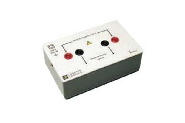
Murata Power Solutions Digital Shunt
- Output: 50 A, 50mV
- Best for: Measuring DC currents from 5A to 1200A

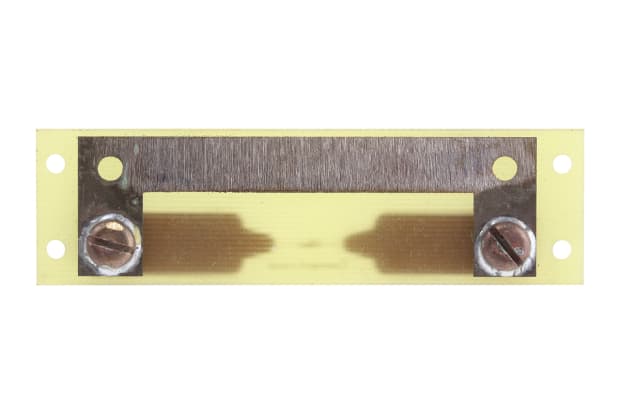
GILGEN Muller & Weigert Plate Shunt
- Output: 100 A, 60mV
- Best for: Measuring higher currents with DQN moving-coil instruments
Chauvin Arnoux Plate Shunt
- Output: 10 A, 100mV
- Best for: Measuring currents up to a rating of 10A with a high level of accuracy
Electrical Shunts in Circuits
Measuring electrical current flowing through a circuit is essential for monitoring performance, diagnosing issues, and ensuring safety in various applications. One of the most effective methods for current measurement is using electrical shunts. Shunts allow for indirect measurement by determining the voltage drop across a precision resistor, in accordance with Ohm’s Law. This voltage drop directly correlates to the current passing through the circuit, enabling accurate calculations of current flow.
The placement of the shunt within the circuit is critical for obtaining reliable measurements. It is advisable to position the shunt as close to the ground reference point as possible, especially when there is a shared ground between the circuit and the measurement device. This strategic placement helps protect the ammeter from common-mode voltage, which can lead to inaccurate readings or even damage to the measurement device.
In situations where isolation is necessary, you may need to isolate the shunt from the ground or incorporate a voltage divider for added protection. This approach ensures that the measurement remains accurate, and that the device is safeguarded from potential voltage spikes.
Shunt resistors offer several benefits for current measurement in electrical circuits:
- Indirect Measurement: By measuring the voltage drop across the shunt, you can determine the current without interrupting the circuit, minimising disruptions to the system's operation.
- Versatility: Shunts can be used for both AC and DC current measurements, making them suitable for a wide range of applications.
- Cost-Effectiveness: Shunt resistors are generally affordable and readily available, providing a budget-friendly solution for current measurement needs.
- High Precision: With proper calibration and placement, shunt resistors can deliver highly accurate current readings, essential for applications like battery management and power monitoring.
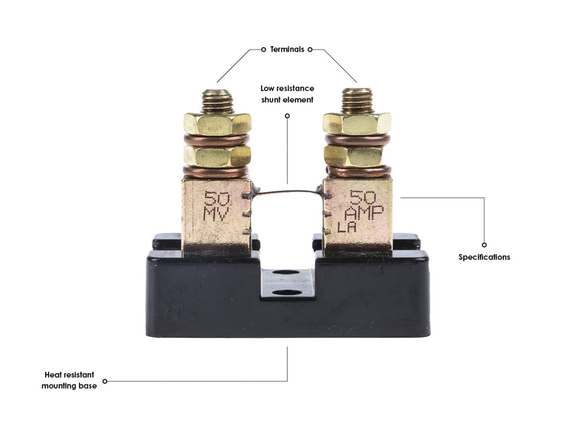
Refer to the diagram below to help identify the various components of a shunt:
DC Panel Ammeter Shunts
DC panel ammeter shunts are essential devices widely used in electrical systems for accurately measuring high current values that exceed the capacity of standard ammeters. By diverting a small portion of the current through the shunt, these devices allow for precise current measurement without interrupting the main circuit. This indirect measurement is crucial in applications where high currents are common, such as in battery management systems and industrial machinery.
The operation of a DC panel ammeter shunt relies on the principle of creating a known resistance in the circuit. The resistance is set to ensure that the resulting voltage drop can be measured accurately without disrupting the overall circuit operation. According to Ohm's Law, the voltage drop across the shunt is directly proportional to the current flowing through it. This relationship enables users to identify the correct current levels based on the voltage drop measured across the shunt.
How Does a Shunt Work?
Shunt resistors differ significantly from standard resistors in their design and application. They are engineered to provide high precision measurements while maintaining a minimal ohmic value. To achieve this, a Kelvin connection is often recommended, which helps eliminate the effects of lead resistance and enhances measurement sensitivity.
Several reversible and irreversible factors can influence the performance of a shunt resistor. Mechanical, electrical, and thermal loads can lead to long-term stability issues and irreversible changes in resistance. The Temperature Coefficient of Resistance (TCR) is a key parameter, expressed in parts per million per degree Celsius (ppm/°C), indicating how much the resistance value varies with temperature fluctuations. Similarly, the Power Coefficient of Resistance (PCR), measured in ppm/W, describes how the resistor's performance changes with the power it dissipates.
Electrical shunts are primarily used to protect speed controllers from loads that draw excessive current, which can lead to overheating and failure. By disconnecting the shunt from the sense line, the speed controller can operate at maximum power without voltage drop. However, this practice can be risky if the load exceeds the controller's capacity.
High-precision current shunts are also utilised in bench testing equipment. When combined with a sensitive voltmeter, these shunts allow for accurate assessment of current levels flowing through a circuit. This method provides a safer alternative for measuring larger currents compared to standard multimeters.
How to Wire a Shunt
Wiring a shunt correctly is crucial for accurate measurements. Begin by following the manufacturer's instructions to ensure compatibility between the ammeter and shunt, particularly regarding their millivolt ratings.
- Connect the Shunt: Attach the shunt to the negative cable that connects the battery bank to the electrical circuits. Identify the negative lead from the battery to the circuits or fuse box.
- Adjust Connections: To measure the current consumed by a connected device supplied by the alternator, adjust the negative connections on the battery to correspond with the shunt. Use a suitably thick cable to connect the other side of the shunt to the battery's negative terminal.
- Mounting: Securely mount the shunt in an area free from the risk of shorting cables. You may need to cut the negative cables for easier installation and create a tight hole for panel mounting the ammeter.
- Ensure Correct Wiring: Verify that the shunt is in series with the load and that the ammeter is wired in parallel with the shunt. The shunt should not connect to the ground.
- Power Up: Once the wiring is complete, power the circuit to begin taking meter readings. Avoid switching on the power if measuring the resistance level.
How to Calculate Current Using a Shunt
Calculating current using a shunt resistor is a straightforward process that leverages the principles of Ohm’s Law. Shunt resistors are essential components in electrical circuits, allowing for the measurement of high current values that exceed the capabilities of standard ammeters. By measuring the voltage drop across the shunt, you can determine the current flowing through the circuit. This method is widely used in applications such as battery management systems, power monitoring, and industrial automation.
To effectively calculate the current using a shunt resistor, follow these steps:
Step One: Understand Ohm’s Law
Begin by writing down Ohm’s Law, which states:
V = I × R
In this equation, V represents the voltage drop across the shunt resistor, I is the current flowing through it, and R is the resistance of the shunt. This fundamental relationship is crucial for calculating current accurately.
Step Two: Substitute the Known Values
Next, substitute the known values of voltage (V) and resistance (R) into the equation. For example, if the voltage drop across the shunt is measured at 10 millivolts (mV) and the shunt resistance is 0.1 ohms, the equation would look like this:
10mV= I × 0.1Ω
Step Three: Solve for Current
To find the current, rearrange the equation to isolate I:
I = V / R
In this example, the calculation would be:
I* *= 10mV / 0.1Ω = 0.1A or 100mA
This result indicates that the current flowing through the circuit is 100 milliamperes.
When using a shunt resistor, it is essential to ensure that the resistor's value is accurately known and calibrated. This precision is critical for obtaining reliable current measurements, especially in applications involving high currents or sensitive electronic components. Additionally, the shunt resistor should be selected based on the expected current range to minimise power loss and ensure safety.


